Description
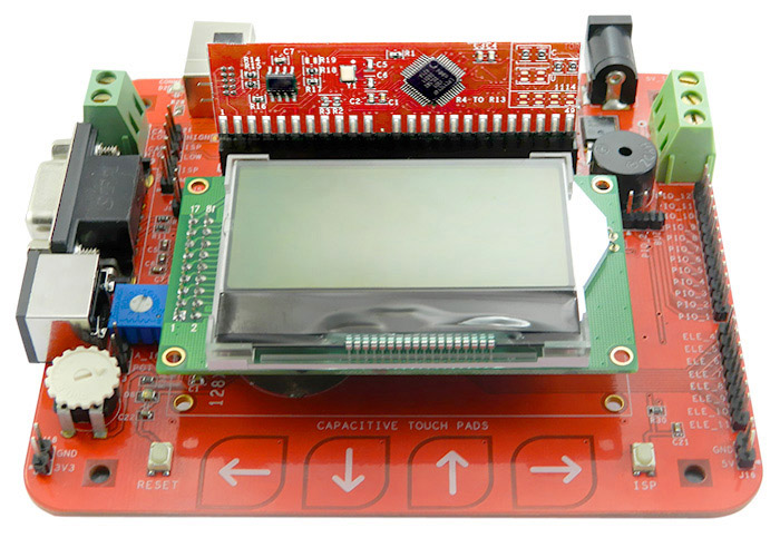
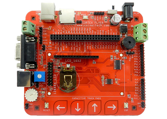
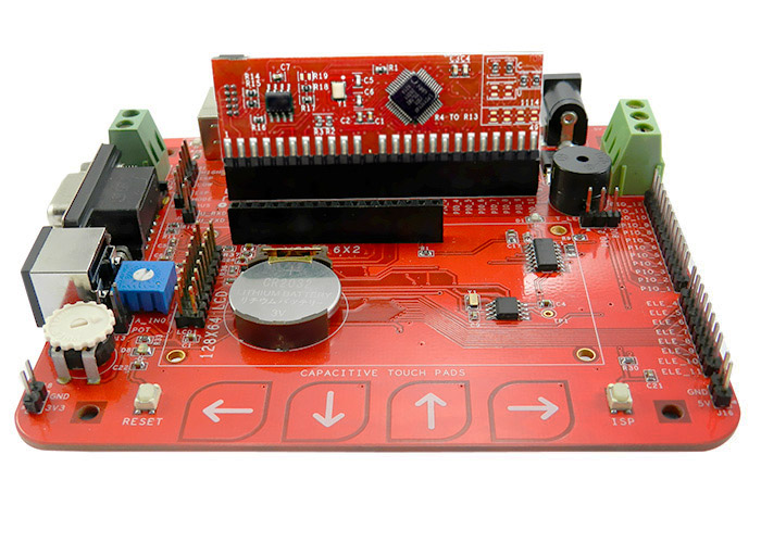
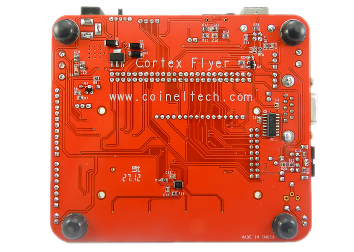
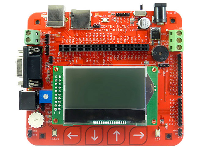
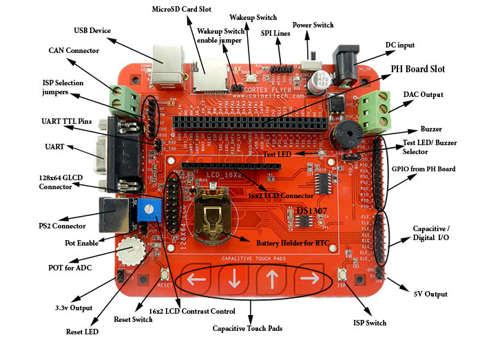
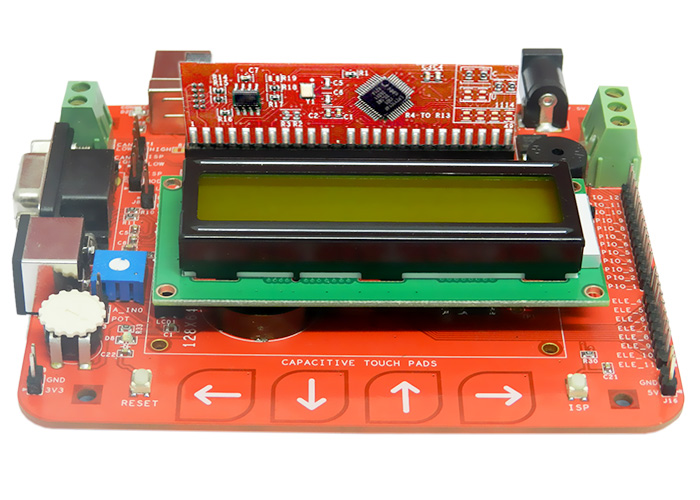
Cortex Flyer Base Board can be used as a general purpose peripheral board for various pluggable headers (PH Boards) available for different Cortex based microcontrollers. This board can also be used with other controllers that use same pinout configurations required for Cortex Flyer.
The Cortex Flyer can be used by professionals and hobbyist who prefer to have options for different controllers while having same peripheral connectivity.
The cortex Flyer along with the PH Boards is a very cost effective option and serves as a perfect platform to try your hands on different controllers based on Cortex M0, Cortex M3, ARM7 etc
The microcontroller that is used along with the Cortex Flyer can also be debugged/programmed with various other debuggers/programmers that support standard SWD connectivity options.
You can choose the PH Boards that you need from the selection option above.
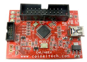
You might also have to buy SWD (CoiNel CoLink Ex Cortex JTAG/SWD Debugger).
Features of Cortex Flyer
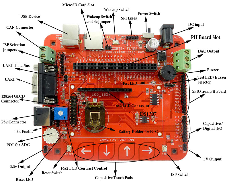
- 50 PIN 2.54 mm Female Header for PH Board Connectivity
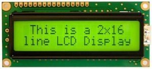
- 16 PIN 2.54 mm Header for 16×2 (HD44780) Based LCD with contrast adjustment POT
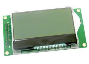
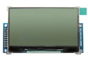
- 18 PIN 2.54 mm Header for Graphical LCD Connectivity.
- 18 PIN 2.54 mm Header for Graphical LCD Connectivity.
- Header can be used as IO also.
- Backlight Control option (See PH Board Connections for details).
- On Board Power for 3.3V and 5V
- Can be powered by USB and Adaptor.
- RTC (DS1307) with CMOS Battery Backup. Interface: I2C
- External DAC (10bit), 2 Channel. Interface: SPI
- 4x Capacitive Touchpad.
- Max 8 Touch pads can be used. 6 can be connected from outside.
- Touch Pads can also be used as IO (12 IO, 4 of which are used for onboard touchpad)
- On Board Buzzer and Test LED.
- PinOut for SPI, I2C
- PinOut from Controller IO (12 IO)
- PinOut from Controller IO (12 IO)
- On Board POT for ADC
- PS2 Keyboard Connectivity Option.
- 1x RS232 Interface. TTL logic also given out.
- CAN PinOut
- 1x USB Device
- Micro SD Connectivity Option.
- Switches for Wakeup, Reset and ISP.
- ISP options via UART, USB, CAN.
- ISP mode used depends of PH Boards used.
- Currently tested for UART.
- Board Specifications.
- Solder Mask: Red
- Board Dimensions: 115 x 100 mm
- Finish: ENIG
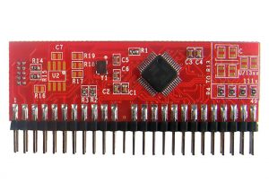
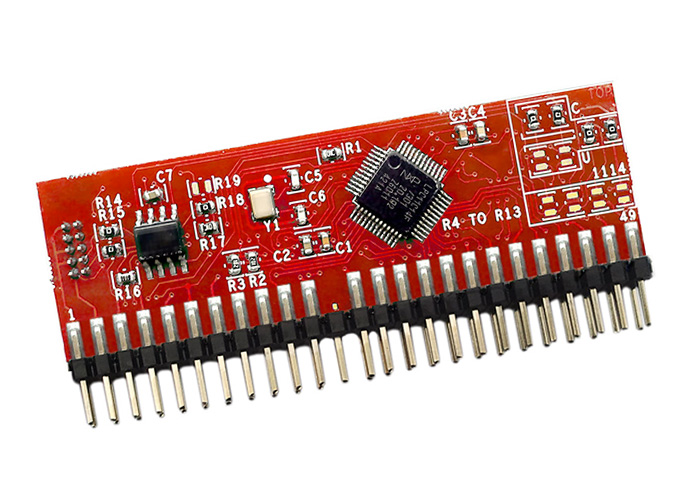
The list of PH Boards that support the Cortex Flyer is given below
| Cortex M0 | Cortex M3 | |
 |
|
|
| PH Board: | LPC1114 PH Board | LPC11Cxx PH Board | LPC11U24 PH Board | LPC1343 PH Board |
| Make/MCU: | NXP/LPC1114 | NXP/LPC11Cxx | NXP/LPC11U24 | NXP/LPC1343 |
| Processor/Core: | Cortex M0 | Cortex M0 | Cortex M0 | Cortex M3 |
| Debugger Connectivity: | 10 Pin 1.27mm SWD Box Header | 10 Pin 1.27mm SWD Box Header | 10 Pin 1.27mm SWD Box Header | 10 Pin 1.27mm SWD Box Header |
| Board Dimensions: | 64 x 20 mm | 64 x 20 mm | 64 x 20 mm | 64 x 20 mm |
- Note: You will need to have atleast one of the above mentioned PH Board to be able to work with Cortex Flyer
ISP Programming
Programming can be done through the on chip boot loader using UART interface (UART0) and USB. You will need a Cortex Flyer Base Board for ISP programming. The board is tested for ISP through UART only.
The tool used for programming via UART is Flash Magic
LCD Support Details
Debugger/Programmer Support
 |
|
Reviews
There are no reviews yet.